


")
Have you ever flipped a light switch at the bottom of the stairs and then walked up only to flip a completely different switch at the top to turn the same light off? That’s a 3 way switch in action — and if you’ve ever tried to wire one yourself, you already know it can feel like solving a puzzle.
A 3 way switch wiring diagram is a visual map that shows exactly how to connect the switches, wires, and light fixture so everything works together. Understanding this diagram is the key to doing the job right the first time. Whether you’re replacing old switches, adding a new light circuit, or simply trying to understand what’s going on inside your walls, this guide walks you through every step in plain language.
What Is a 3 Way Switch and How Does It Work?
Before you can follow a 3 way switch wiring diagram, you need to understand what makes these switches different from the regular ones you’re used to.
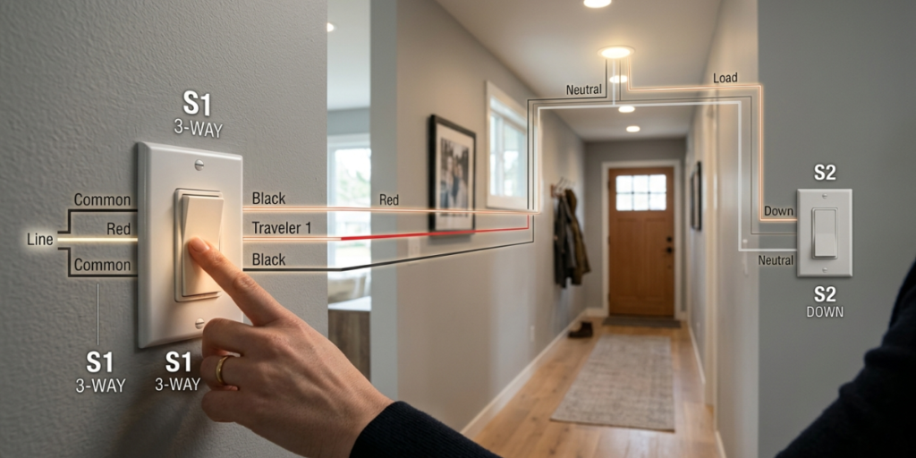
A standard switch has only two terminals — it’s either ON or OFF. A 3 way switch, on the other hand, has three terminals: one common terminal (usually labeled COM or colored black) and two traveler terminals. The travelers are the wires that run between the two switches, while the common terminal is where power either enters or exits.
When you flip a 3 way switch, you’re redirecting the electrical current from one traveler wire to the other. Because both switches share these same travelers, either switch can complete or break the circuit — which is what lets you control one light from two different locations.
Here’s a simple way to think about it: imagine two train switches on the same track. No matter which one you change, the train (electricity) either gets through or it doesn’t. That’s essentially what’s happening inside your walls every time you flip a 3 way light switch.
Key Terminals on a 3 Way Switch
| Terminal | Color/Label | Purpose |
|---|---|---|
| Common | Black screw or COM | Connects to power (hot wire) or to the light |
| Traveler 1 | Brass or gold screw | One of two traveler wires connecting both switches |
| Traveler 2 | Brass or gold screw | The second traveler wire connecting both switches |
| Ground | Green screw | Safety ground wire (bare copper or green) |
Getting these terminals right is the most important part of reading a 3 way switch wiring diagram. If you connect a wire to the wrong terminal, your switches won’t work — or worse, they could create a safety hazard.
The Wires You’ll Need to Know

Before diving into the actual 3 way switch circuit diagram, let’s t
alk about wiring. Most homes built after the 1960s use NM cable (also called Romex), which comes in a few common configurations.
For a basic 3 way switch circuit, you’ll typically work with:
- 14/2 cable — contains a black (hot), white (neutral), and bare copper (ground) wire. Good for 15-amp circuits.
- 14/3 cable — contains a black, white, red, and bare copper wire. The extra red wire serves as the second traveler. This is the cable that runs between your two 3 way switches.
- 12/2 and 12/3 cable — same layout but thicker gauge, used on 20-amp circuits.
The traveler wires are the heart of the 3 way circuit. They’re the two wires running from switch to switch that allow current to jump between the two locations. In a 3 way switch wiring diagram, you’ll almost always see these labeled clearly or drawn in a distinctive color.
Understanding Wire Colors in 3 Way Switch Wiring
Wire color codes matter a lot here. In a typical NM cable setup:
- Black wire = hot (carries live current)
- White wire = neutral (but sometimes re-marked as a hot wire in switch loops)
- Red wire = used as the second traveler wire
- Bare copper = ground
One thing that trips up a lot of DIYers: in a switch loop, the white wire is sometimes used as a hot wire and should be marked with black tape to show this. Always check what role each wire is playing before touching anything.
The Most Common 3 Way Switch Wiring Diagram Explained

There are a few different ways to wire a 3 way switch, depending on where the power enters your circuit. The most common setup is power at the first switch, with the light fixture at the end of the circuit.
Here’s how this standard 3 way switch wiring diagram works step by step:
Step 1 — Power enters Switch 1. Your 14/2 cable from the breaker box arrives at the first switch box. The black wire connects to the common terminal on Switch 1.
Step 2 — Traveler wires connect the two switches. A 14/3 cable runs from Switch 1 to Switch 2. The black and red wires from this cable connect to the traveler terminals on both switches. It doesn’t matter which traveler goes to which brass screw, as long as both switches share the same two wires.
Step 3 — Power leaves Switch 2 toward the light. The common terminal on Switch 2 connects (via the white wire in your 14/2 cable) to the black wire going up to the light fixture. The white wire of this cable connects to the neutral wire at the light.
Step 4 — Grounds are connected. Bare copper ground wires connect to the green screws on both switches and continue to the light fixture’s ground.
The result: flip either switch, and you change whether the travelers are completing the circuit or not — giving you full two-location light control.
3 Way Switch Wiring Diagram: Power at the Light Fixture

Another very common setup you’ll encounter is power entering at the light fixture rather than at one of the switches. This version of the 3 way switch wiring diagram looks a little different but works the same way.
In this layout, the power cable (14/2) arrives at the ceiling box where your light fixture is. From there, a 14/3 cable drops down to Switch 1, and another 14/3 cable connects Switch 1 to Switch 2.
The tricky part here is that you’re running power down to the switches and then routing the switched hot wire back up to the light. Because of this, you’ll often need to use the white wires as hot wires in the switch legs, which means they must be re-marked with black or red tape to indicate they’re carrying live current.
Many electricians and DIYers find this configuration a bit more confusing to follow in a 3 way switch wiring diagram, so it helps to label every wire before you disconnect anything when replacing existing switches.
Tips for Getting This Right
- Always turn off the breaker and verify with a non-contact voltage tester before touching any wires.
- Take a clear photo of existing wiring before you disconnect anything.
- Use electrical tape to re-mark any white wires used as hot conductors.
- Double-check which screw is the common terminal — it’s usually a different color than the traveler screws.
How to Wire a 3 Way Switch: Step-by-Step Installation

Now that you understand the diagram, here’s how to actually put it into practice. This applies to a standard power at first switch setup.
What you’ll need:
- 14/2 and 14/3 NM cable (or 12/2 and 12/3 for 20-amp circuits)
- Two 3 way switches
- Wire stripper, voltage tester, needle-nose pliers
- Electrical tape and wire connectors (wire nuts)
- Screwdrivers (flathead and Phillips)
Installation Steps:
- Turn off the breaker for the circuit you’re working on. Test with a voltage tester to confirm there’s no power.
- Run your cables. You’ll need 14/2 from the panel to the first switch box, 14/3 between the two switch boxes, and 14/2 from the second switch box to the light fixture.
- Wire Switch 1. Connect the black wire from the panel to the common terminal. Connect the black and red travelers (from the 14/3 cable going to Switch 2) to the two traveler terminals.
- Wire Switch 2. Connect the black and red travelers from Switch 1 to the two traveler terminals on Switch 2. Connect the black wire going to the light to the common terminal.
- Wire the light fixture. Connect the black (switched hot) to the fixture’s black wire and white neutral to white neutral. Connect grounds.
- Restore power and test. Flip each switch independently to confirm the light responds correctly from both locations.
3 Way Dimmer Switch Wiring

Thinking about installing a 3 way dimmer switch instead of a standard 3 way? This is a popular upgrade for living rooms and dining areas — but there are a few important differences to know.
Most 3 way dimmer switches require that only one of the two switches is a dimmer. The other switch must be a compatible companion switch (sometimes called an accessory switch), not a regular 3 way switch. Check the packaging carefully — using two dimmers in the same circuit, or pairing a dimmer with a regular switch, won’t work correctly and can damage the dimmer.
The wiring for a 3 way dimmer follows the same general 3 way switch wiring diagram — common terminal to common terminal, travelers to travelers. However, some dimmer models have specific requirements about which end of the circuit they need to be installed on (the power-in end), so always read the manufacturer’s instructions.
LED bulbs and dimmer compatibility is another thing worth checking. Not all LED bulbs are dimmable, and not all dimmers play nicely with LED lighting. Look for LED-compatible dimmers and dimmable LED bulbs to avoid buzzing, flickering, or premature bulb failure.
Troubleshooting a 3 Way Switch That Isn’t Working

You’ve wired everything up, restored power, and… nothing works as expected. Don’t panic — 3 way switch troubleshooting usually comes down to a few common mistakes.
Problem 1: Neither switch turns the light on. This usually means the common terminal on one or both switches is connected incorrectly. The common is where the circuit actually feeds power in or sends it out — if it’s wrong, the circuit can’t complete.
Problem 2: One switch works but the other doesn’t. Check the traveler wires. If both travelers are connected to the same terminal on one switch (instead of one to each traveler screw), only one switch position will work.
Problem 3: Light stays on or off no matter what. This often points to a wiring reversal — a traveler wire accidentally ended up on the common screw, or vice versa. Compare your wiring against a trusted 3 way switch wiring diagram and check each connection.
Problem 4: Switches work but the light flickers. Loose wire connections are the most common culprit. Turn the power off and check that all wire nuts are snug and all screw terminals have wires tightened firmly underneath them.
Frequently Asked Questions About 3 Way Switch Wiring
Q1: Can I use regular wire for a 3 way switch circuit? For the run between the two switches, you need 14/3 (or 12/3) cable because you need that extra red wire as the second traveler. Using standard 14/2 between the switches won’t give you enough conductors to wire the circuit correctly.
Q2: Does it matter which traveler wire goes to which terminal? No — the two traveler terminals on a 3 way switch are interchangeable. What matters is that both switches are connected to the same two traveler wires. If Switch 1 uses black and red travelers, Switch 2 must connect to those exact same black and red wires.
Q3: What is the common wire in a 3 way switch circuit? The common wire is the one that brings power into the first switch (from the breaker) and carries switched power out of the second switch (toward the light). It always connects to the common terminal (the darker-colored screw) on each switch.
Q4: How do I know which screw is the common terminal? The common terminal is almost always identifiable by its darker screw color — typically a black or very dark brass screw. Many switches also have the word “COM” or “COMMON” printed on the back near that terminal.
Q5: Is a 3 way switch the same as a double-pole switch? No. A 3 way switch is used to control one light from two locations. A double-pole switch controls a single device but interrupts both the hot and neutral wires simultaneously — it’s used in 240-volt applications like large appliances. They may look similar but serve completely different purposes.
Conclusion
Once you understand the logic behind it, a 3 way switch wiring diagram isn’t nearly as intimidating as it first looks. The key is knowing your three terminals (common and two travelers), using the right cable (14/3 between the switches), and making sure each wire lands on the right screw.
Take your time, turn off that breaker, and refer to a clear diagram as you work through each connection. Whether you’re doing a simple switch replacement or running a fresh circuit from scratch, following the correct 3 way switch wiring principles will give you a safe, reliable result that works every single time you flip the switch — from wherever you’re standing.
When in doubt, call a licensed electrician. Electrical work done incorrectly can be a serious fire and safety hazard, and there’s absolutely no shame in getting a professional involved. electrical safety guidelines
")
")


